Using the New Project Wizard to create a Project with USBDM support
Support in Codewarrior V10.x is available as follows:
- RS08
- HCS08
- Coldfire V1
- Coldfire V2,3,4.
- Kinetis
- DSC support in very limited - Debugging may be unreliable.
USBDM is fully supported by the Codewarrior New Project Wizard. The following shows the required initial steps of creating a USBDM project using the wizard.
- Start the wizard from the pop-up menu in the Project Explorer window or from the main Menu, for example New->Bareboard Project.

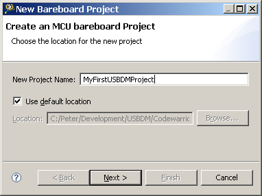
- Choose a suitable name for the project.
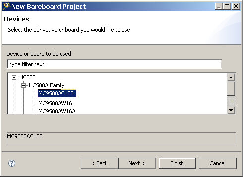
- Select the target device or board for development.
- Select the USDBM connection and any other connections required.

The remaining pages of the Wizard are independent of the target connection and allow a range of options and alternative for the project. If only a basic project is needed it is sufficient to click Finish now. This will create a new project with a Remote System connection for USBDM.
It may be desirable to change some of the default settings to suit your BDM. This will be the case if you wish to trim the target clock or use the power supply features of the BDM. The following section describes the USBDM specific settings available.
The Remote System dialogue for USBDM may be accessed in two ways (that I know of!):
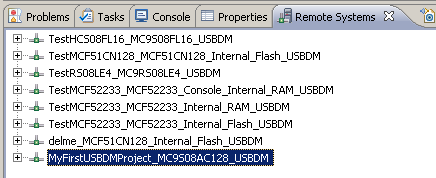
- Locate the connection in the Remote Systems tab which is usually one of those at the bottom of the Eclipse Workspace: There will be a line for each remote entry in the the workspace. Note that it possible to share these systems between different projects but they must have the same target device. For the example created above, this Remote System will be called MyFirstUSBDMProject_MC9S08AC128_USBDM.
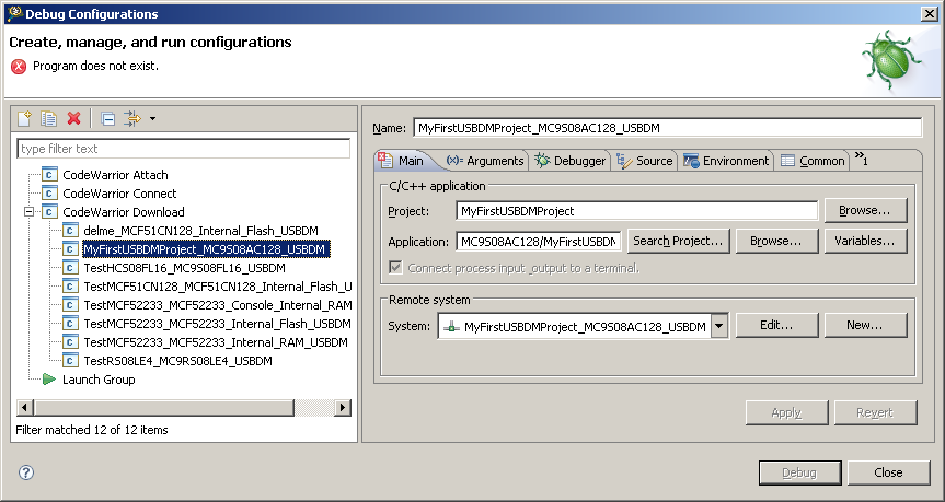
- Alternatively, locate the connection through the debug settings for the project:
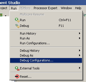
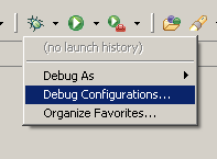
To view the USBDM Debug Options select the Debug Configuration at the left and then click on the Edit button in the Remote Settings area.
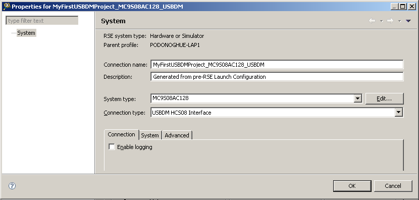
The various options are discussed in the following sections
Some of the following options may be absent from the dialogue for a particular target.
Some options may have no effect depending upon the hardware capabilities of the BDM interface connected during the actual debugging session.
Common options
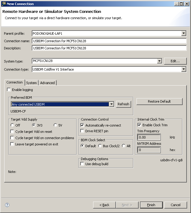
- Connection Name: An arbitrary name used to identify this target connection.
- Description: Descriptive text - change as desired to describe the connection.
- System type: This identifies the target device e.g. MCF51CN128 etc
- Connection type: This allows selection between all the connections available for the device chosen above.
The USBDM connections available are:- USBDM RS08 Interface
- USBDM HCS08 Interface
- USBDM Coldfire V1 Interface
- USBDM Coldfire V2,3,4 Interface
- USBDM ARM interface
USBDM Options for Kinetis targets only.
Some options may have no effect depending upon the hardware capabilities of the BDM interface connected during the actual debugging session.
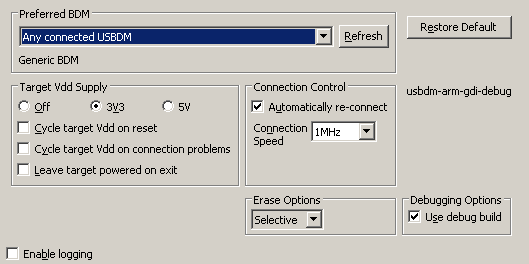
Preferred BDM - Allows selection of preferred BDM when multiple are connected when launching a debug session 
|
Target Vdd Supply - Enables supply of Target Vdd from the USBDM module 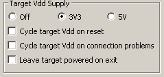
|
Connection Control 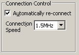
|
Erase Options 
This option controls how the device is erased before programming. Not all options will be available with a every target type.
|
Common Options
|
| This completes the setting up of a launch configuration . You may proceed directly to debugging with the Debug button or just Close the dialogue. Later debugging sessions may be started by selecting the Launch configuration directly from the debug drop-down menu. | 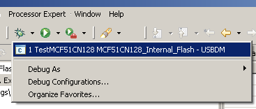
|
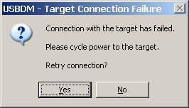
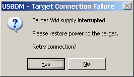
Popups
| 
|
| 
|
Manually Creating a Launch Configuration for USBDM
Since USBDM is now supported by the Codewarrior New project Wizard the following process is no longer necessary.
It is included as a reference to what the various setting do rather than as a necessary process.
The following describes manually creating a custom Debug Launch Configuration. The configuration can then be used to launch a debug session.
The following outlines the steps required to create the Debug Launch Configuration. This should be read in conjunction with the Codewarrior V10 quickstart manual. It is assumed that a suitable application has been created beforehand.
The following example is for a Coldfire V1 device. The settings for a RS08 or HCS08 device would be almost identical. The required changes are indicated where appropriate.
Programming the flash of Coldfire V2,3,4 devices is not supported so some sections are not appropriate to those devices. It is necessary to program the device using the Flash programmer before debugging or as a autorun task setup as part of the Debug Launch Configuration.
| Select an existing application to configure for debugging. | 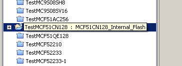
|
| Open the Debug Configuration Dialogue by selecting Run->Debug Configurations... from the menu or clicking on the small arrow to the right of the debug icon. The dialogue shown below will open: | 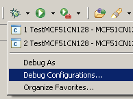
|
.png)
|
| Make sure Codewarrior Download is selected in the panel at left and then click the New button/icon to create a new empty configuration. This configuration will be partially completed providing you have selected an existing application at the first step above. |
_V10_1.png)
|
| Check the dialogue contents and rename the launch configuration if desired e.g. add the USBDM suffix as a reminder that this configuration is intended for the USBDM debugger.. Click on the New Button in the Remote System area |
| Select Hardware or Simulator in the dialogue as shown and Click Next | 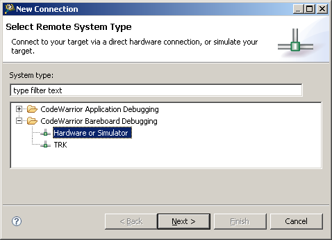
|
Set up the following option:
| 
|
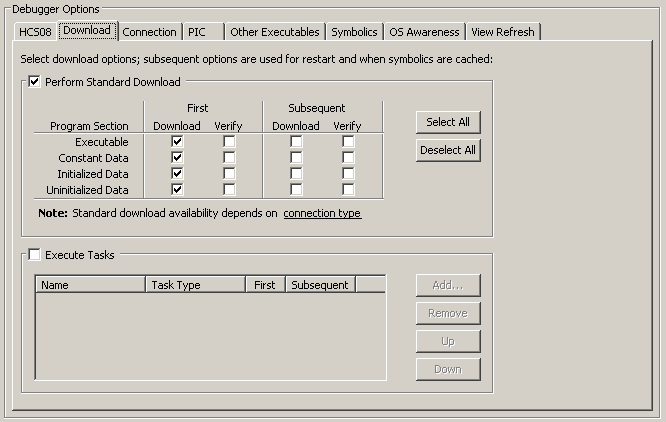
Programming Options for RS08, HCS08 or Coldfire V1
| These option should already have been set correctly by the New Project Wizard. Select the Debugger and then the Download tab and modify the contents as shown below : (Make sure Execute Tasks is unselected.) |
|
The USBDM GDI dll has a built in flash programmer that handles the programming of the target non-volatile memory (in RS08, HCS08, CFV1 and Kinetis targets). The options selected cause USBDM to program the target on initial download with a new debug session but not to re-program if the debugger session is re-started. This prevents the Flash from being needlessly re-programmed. The verify options may be selected but USBDM already verifies programming so this is unnecessary. Also, it is possible for the Codewarrior verify to fail as USBDM may modify the data programmed to the target memory to support trimming of the target clock or disabling target security to allow debugging. |
