Installing the USBDM firmware to the FRDM board allows the on-board target chip to be programmed using the USBDM tools. This does not require any hardware modification of the board. This is useful as an initial test of the USBDM system.
Before using the FRDMxxxx board as an external Kinetis programmer it is necessary to make some hardware modifications.
Note: The following describes the process for a KL25. A very similar approach works with the other FRDM boards that use OpenSDAv1. This includes the following
FRDM-KE02Z, FRDM-KE03Z, FRDM-KE02Z40M, FRDM-KE04Z, FRDM-KE06Z, FRDM-KL02Z, FRDM-KL05Z, FRDM-KL25Z, FRDM-KL26Z, FRDM-KL46Z and FRDM-K20D50M
For boards using OpenSDAv2.0 a different firmware is provided but the process is similar. The only current boards is:
FRDM-K64F
For boards using OpenSDAv2.1 a different firmware is provided but the process is similar. The only current boards is:
FRDM-K22F
The above steps are described in the following:
Installing USBDM firmware on FRDM-xxxx
Complete the USBDM Software Installation and USB Driver Installation before doing the following:
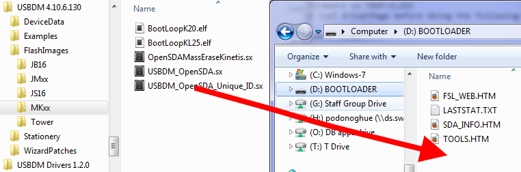
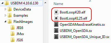
- Locate the various USBDM_OpenSDAxxx.xxx files in the USBDM firmware folder. This folder may be opened from the Windows Start Menu.
- Navigate to the MKxx folder.
| Open from Start Menu | Locate MKxx folder |
- There are six firmware images for the FRDM boards. These are OpenSDA applications.
- USBDM_OpenSDAv1.sx - OpenSDAv1 Image with a fixed USB ID (FRDM-K2L25 etc)
- USBDM_OpenSDAv1_Unique_ID.sx - OpenSDAv1 Image with a USB ID that is determined from the device unique ID.
- USBDM_OpenSDAv2_0.bin - OpenSDAv2.0 Image with a fixed USB ID (FRDM-K64)
- USBDM_OpenSDAv2_0_Unique_ID.bin - OpenSDAv2.0 Image with a USB ID that is determined from the device unique ID.
- USBDM_OpenSDAv2_1.bin - OpenSDAv2.1 Image with a fixed USB ID (FRDM-K22)
- USBDM_OpenSDAv2_1_Unique_ID.bin - OpenSDAv2.1 Image with a USB ID that is determined from the device unique ID.
Using the '..._Unique_ID' version of these images means that each BDM will be assigned a unique and consistent serial port number irrespective of which USB port is used. This really only makes a difference if you have multiple BDMs and you don't want to play "find the com port number" when you plug the BDM into a different USB port under windows.
In a laboratory environment it may be better to use the first image as otherwise a different serial port number will be assigned whenever a different BDM is plugged in.
These are OpenSDA applications and installation uses the usual OpenSDA bootloader process:
- Unplug the Freedom board.
- Whilst holding the reset switch depressed, plug in the Freedom board. The green LED should start blinking at a rate of about 1Hz.
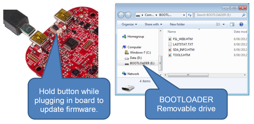
- Open a file explorer and locate the USB drive that has now appeared. It will have the drive name "BOOTLOADER".
- Drag the file USBDM_OpenSDAxxxxx.sx to the USB drive and wait a short while. The OpenSDA bootloader on the Freedom board will program the USBDM firmware into the MK20 debugger chip on the board.
- Remove and re-plug the Freedom board. The board will now appear as a USBDM device and USBDM driver installation will occur.
You can test the interface by trying the stand-alone ARM flash programmer that is part of the USBDM installation. If you have already modified the hardware it will be necessary to place a jumper on J-11 to allow the programming of the target chip on the Freedom board.
Hardware Modifications to FRDM-KL25Z
Before using the FRDMxxxx board as an external Kinetis programmer it is necessary to make some hardware modifications. The on-board chip may be programmed without modification.
The modifications detailed below are for the FRDM-KL25Z board. Similar modifications are necessary for the other FRDM boards but the details will vary. Some of the early revisions of the FRDM boards have hardware errors that make it difficult to use as external programmers. I recommend FRDM-KL25 or FRDM-K20 boards.
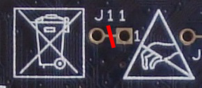
- Cut the PCB trace on the bottom of the board under J11. This trace connects the SWD hardware to the MKL25Z128M4 device on the board.
It must be opened to allow an external target to be connected without interference from the on-board chip (but see comments below).
Connection to the on-board target may be restored by adding pins and a jumper at J11 on the top of the board.
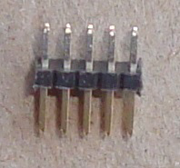
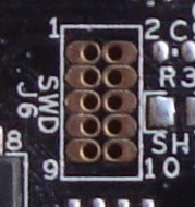
- Add a 10-pin connector at location J6 which is also marked SWD. Do not confuse this with the similar connector at J8 marked SDA/SWD.
A suitable connector would be Element-14 #681-1184. This is an unprotected header.
- Obtain a suitable 10-pin to 10-pin programming cable to connect to the target. The cheapest I've found has been from Element14 #2144328.
Debug cable and FRDM-KL25 with SWD connector & J11 jumper pins highlighted.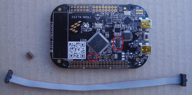
Programming an External Device
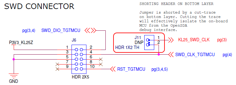
Jumper J-11 isolates the on-board device from the SWCLK signal on the programming interface. This effectively disables the SWD interface on this device. Unfortunately this does not entirely isolate the on-board device from the programming interface - RESET is still connected.
Due to this, it is important that the on-board device contains a valid program so that it does not affect the programming of an external device by asserting the reset signal because of a watch-dog timeout or program crash.
It is recommended to program the BootLoopXX.sx file or similar harmless program to the on-board device before using the external interface. The USBDM ARM Flash programmer is a convenient way to do this. Program with the J-11 jumper present. After doing this, remove the jumper on J-11 to use the external programming interface.